Civil Engineering and Architecture
Architectural Styles Project - Contemporary
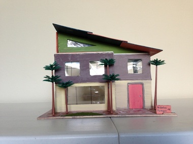
For the first project in CEA, we constructed houses to represent a particular architectural style. By creating this project, we learned what characterizes a specific type of architecture, and distinguish between similar forms, such as between Southern Colonial and Greek Revival. My assigned architectural style was contemporary architecture, which is actually much different compared to its counterpart, modern architecture. While most people intertwine the two when identifying these similar types of architecture, most civil facilities and skyscrapers tend to hold an industrial, "modern" design, while most homes and community facilities tend to hold a contemporary design. Contemporary design is more elemental, eco-friendly, and connects the indoor and outdoor spaces, whereas modern represents a more futuristic, cold, clean slate, and industrial feel.
Surveying Data Project
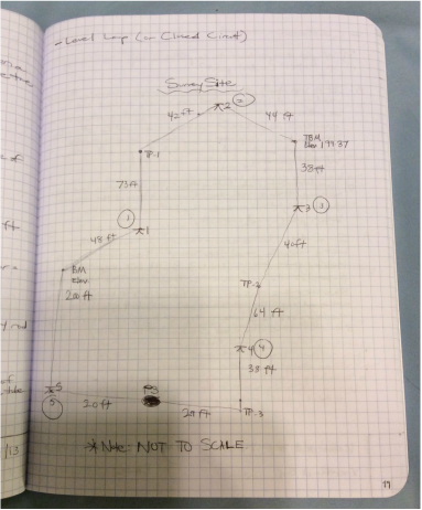
Our second project in CEA was to conduct a land survey of specified points around our school campus. I worked in a group with Hunter Halton, Nicholas Cruz, and Shantell Labajo for this project. We set up our surveying instrument at the benchmark point, located on the far left middle corner, labelled "BM," and recording the stadia readings based on our survey instrument observation, then moved on to repeat the same process for all of the other points on the map. In the process, we recorded the foresight and backsight measurements based on the stadia readings and elevations throughout. At the same time, I sketched lines to approximate the path we had followed throughout the survey, and the picture to the left demonstrates this. To connect this activity to real life, it is important to conduct land surveys before constructing anything on a property because you want to ensure the safety of your building, and ensure that it is evenly levelled in terms of elevation, not sloped. Without land surveys, cities with highly uneven terrain, such as Las Vegas, would have very crooked buildings and uneven streets!
Topographic Map Model Project
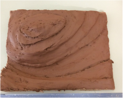
For our class's topography unit, we were required to create a 3D terrain model to display how a hill would look based on specified contour lines and hachure marks on a topographic map. Using pieces of cardboard, and damp clay as a means of simulating the visual appearance of the hill, I worked with Hunter Halton to create this topographic model of the hill. As you can see in the picture, from the bottom, the model starts with a steep decline into a gutter, which contains a stream, (not shown here, only on the map), and then begins an incline up the larger hill to a summit, then leading to yet another decline, this one less steep than the previous one. While making the model and calculations is easy, the process to actually map the hill accurately in reality is very difficult, as many "stations" must be positioned in various locations. Other methods include aerial photography, however these sometimes don't include little details found on the surface level.
Activity 3.4.6 - Landscaping
One activity we worked on after winter break was landscaping. Now that we learned how to survey and create topographic maps, and even conduct soil analyses, we were assigned the Keystone Library Renovation Project to write a report on. This report includes the conditions that the building needs in order to comply with state requirements. The Keystone Library was to be located in a fictional town, Noblesville, Indiana, and the requirements for construction were detailed on their "website." Feel free to browse through this report! It is possible we may create the AutoCAD version of the Keystone Library in the future!
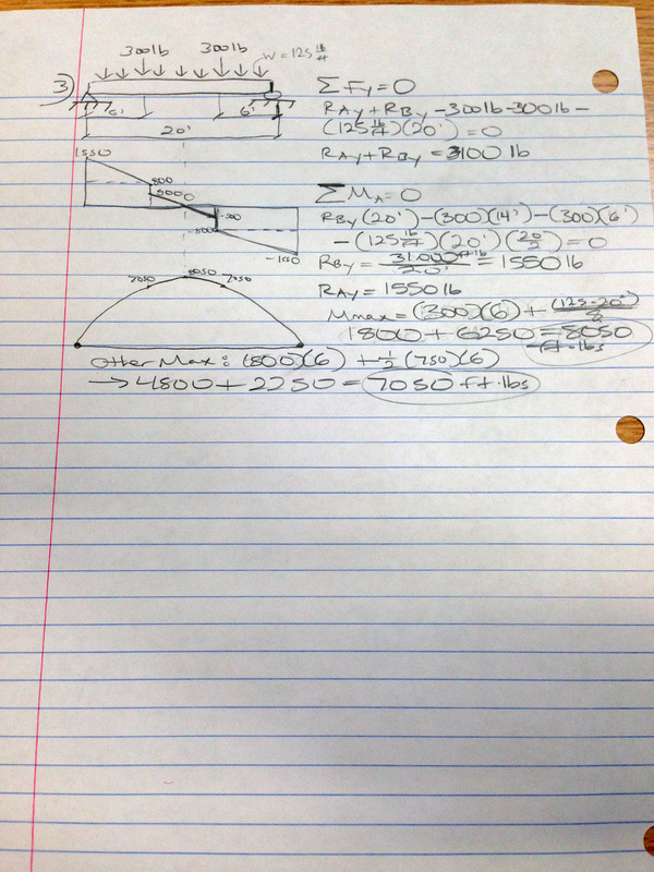
Activity 3.2.3 - Beam Analysis
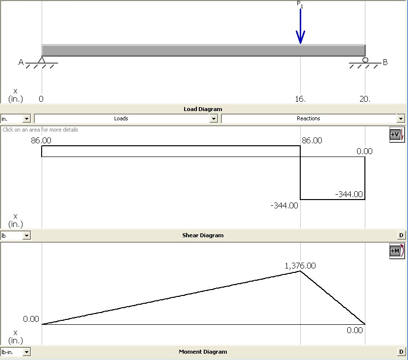
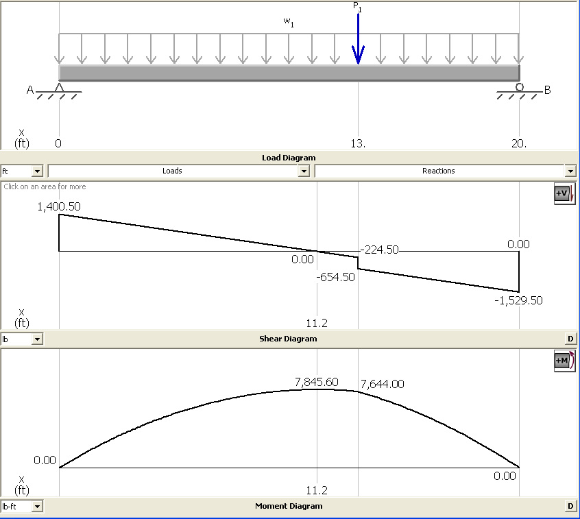
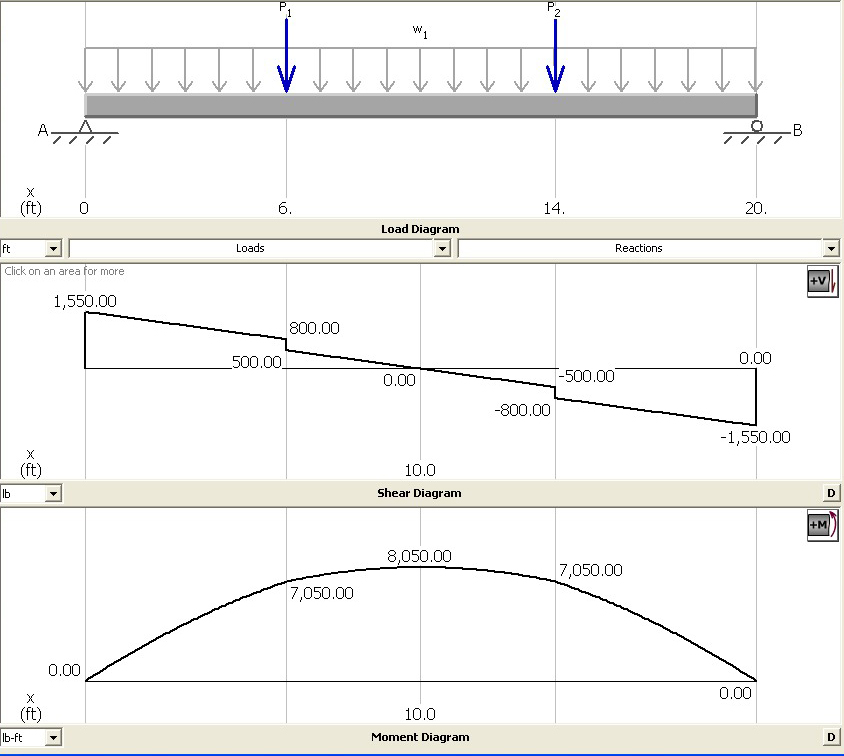
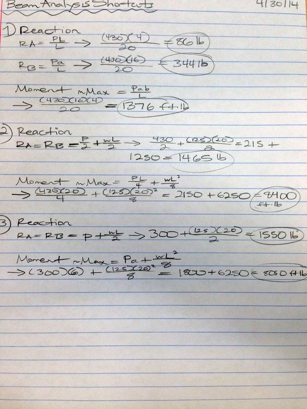
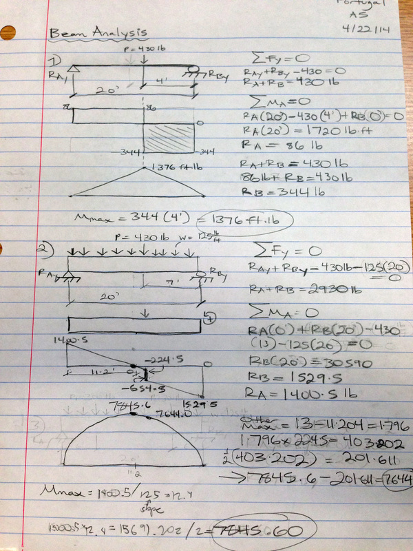
After spring break, our class worked on by far, the hardest activity we've done yet, Beam Analysis. Conceptually, while the engineer identifies and quantifies the design loads that will be imposed on the beam, the structural engineer must then determine the beam strength necessary to resist the applied loads. Maximum resisting forces due to design loads, including the shear and bending moment, must all be calculated. Afterward, the beam is then selected that can safely carry the required shear and bending moment. These two variables can be represented by using shear and moment diagrams. Click on the pictures below to view the MD Solids Diagrams for each exercise as shown below!
Semester Two Final Exam Essay - Rube Goldberg PBL
For our semester two final exam essay component, we had to write about the Spring PBL we had before spring break, which was during the last week of March. In this essay I discuss Rube Goldberg machines and relevance today.
